Chapter 3
Industrial Networks and Protocols
The Packet That Stopped a Press
Drop a packet on an office network. The application retries automatically. The user never notices. Drop that same packet on a real-time industrial network controlling a stamping press. The press hesitates for 10 milliseconds. That hesitation is enough time to produce a defective part or trip a safety interlock, the automatic shutdown triggered when the process moves outside safe parameters. This is why industrial networking is not just a stricter version of IT networking. It is a different engineering discipline built around a different set of requirements. Three structural differences define it. First, determinism: IT networks are best-effort, meaning packets arrive when they arrive. OT networks must guarantee delivery within a fixed time window on every cycle. Time-Sensitive Networking targets latency below 50 microseconds, with jitter (variation in delivery timing between packets) under 100 nanoseconds. A standard IT switch introduces variable delay that is physically tolerable in an office but catastrophic in a control loop. Second, near-zero failure tolerance: IT systems fail gracefully and recover quickly. OT systems are designed to avoid failure entirely. A brief network outage in a chemical plant can trigger an emergency shutdown with real safety consequences. This is why some ICS redundancy protocols achieve zero-millisecond recovery -- not fast recovery, but no detectable failure at all. Third, the physical environment: industrial settings produce electromagnetic threats from motors, drives, relays, and lightning that office buildings don't. Industrial network hardware is built specifically to operate in them, using differential signaling, fiber optics, and ruggedized components that standard IT equipment cannot substitute for.
Modbus and the Fieldbus Era
In 1979, a company called Modicon published a protocol specification that let PLCs communicate with computers over a serial cable. Forty-five years later, Modbus remains the most widely deployed industrial communication protocol in the world. You will encounter it in virtually every industrial environment you work in. As Chapter 1 noted, Modbus was designed for networks where everything on the wire was trusted by definition. Understanding why requires understanding how the protocol actually works. Modbus is a master-slave, request-response protocol. One master device -- typically a SCADA server or HMI -- sends requests. Slave devices (PLCs and field instruments) respond. A slave never sends data unprompted; it only answers when asked. The master polls each slave on a fixed schedule. Three variants exist: Modbus RTU encodes data in binary over RS-232 or RS-485 serial cables (the dominant deployed form), Modbus ASCII uses text encoding (largely obsolete), and Modbus TCP wraps the same protocol in a TCP/IP header on port 502. Function codes define what the master is requesting. FC03 reads holding registers (16-bit values storing analog readings and setpoints) and FC16 writes a block of registers -- these two function codes handle the majority of plant-floor Modbus traffic. The protocol has no authentication, no encryption, and no authorization mechanism. Any device that can send a well-formed Modbus message can command any slave on the network. This is not a vulnerability that can be patched -- it is a fundamental design characteristic of a protocol built for an era when the network itself was the security boundary.
PROFIBUS emerged from a German government research project in the late 1980s and became the dominant European fieldbus. PROFIBUS DP handles factory automation at up to 12 megabits per second, connecting drives, I/O modules, and sensors to PLCs. PROFIBUS PA runs on a single twisted pair at 31.25 kilobits per second, with that one cable carrying both data and power to field instruments in hazardous areas -- a significant practical advantage where running separate power cables is expensive or dangerous. More than 11 million PROFIBUS devices are deployed globally. Foundation Fieldbus went further than either: field instruments running Foundation Fieldbus can execute local control loops inside the device itself, without relying on a central controller to close the loop. Neither PROFIBUS nor Foundation Fieldbus has authentication or encryption built into the base communication protocol, reflecting the same design assumption that shaped Modbus: physical isolation was the security model.
Industrial Ethernet: The Protocols That Run Today's Plants
By the mid-1990s, Ethernet had transformed office networking. Industrial engineers faced an obvious question: could the same cables and switches guarantee the real-time behavior that PLCs require? Standard Ethernet wasn't designed for determinism -- packets competed for bandwidth and arrival times varied. The answer was yes, but only by adding strict protocol rules on top of standard Ethernet hardware. The result was a family of industrial Ethernet protocols, each developed by different vendors for different markets, and each still in widespread use today. EtherNet/IP runs the Common Industrial Protocol (CIP) over standard unmodified Ethernet hardware -- no special cables or switches required. It uses implicit messaging for real-time I/O data over UDP at 1-10 millisecond update cycles, and explicit messaging for configuration and diagnostics over TCP. EtherNet/IP dominates North American discrete manufacturing, automotive assembly, packaging, and material handling. PROFINET is the industrial Ethernet standard developed by Siemens and the PI International consortium, defined under IEC 61158. Its RT mode achieves 1-10 millisecond update rates on standard switches. Its IRT mode, requiring PROFINET-aware hardware, reaches update rates as fast as 31 microseconds for motion control applications. PROFINET includes a safety profile called PROFIsafe, which allows safety controllers and standard controllers to share the same network infrastructure while meeting IEC 61508 safety function certification requirements. PROFINET dominates European manufacturing and all Siemens environments globally. DNP3, dating from the early 1990s, was designed for electric utility SCADA systems running over unreliable links: dial-up modems, radio, and leased telephone lines. It adds timestamps to every data point so that substations miles apart can correlate events, and it allows RTUs to push data when values change rather than waiting to be polled -- a critical capability when communication links are intermittent. DNP3 also runs over TCP/IP Ethernet and dominates electric utilities, water and wastewater systems, and oil and gas pipelines across North America. IEC 61850 is the international standard for communication in electrical substations. Its GOOSE (Generic Object-Oriented Substation Event) messaging broadcasts protection relay decisions across a Layer 2 Ethernet segment in under 4 milliseconds -- fast enough for real protective relay operations, with no IP routing involved and no polling cycle to wait through. Multiple protocols coexisting in the same facility is the norm: a plant built with Allen-Bradley equipment runs EtherNet/IP, a Siemens plant runs PROFINET, and the electric utility feeding the plant uses DNP3. Understanding which protocols are present is a prerequisite for both operations and security monitoring. You cannot interpret traffic you haven't learned to identify.
OPC and OPC UA: Solving the Integration Problem
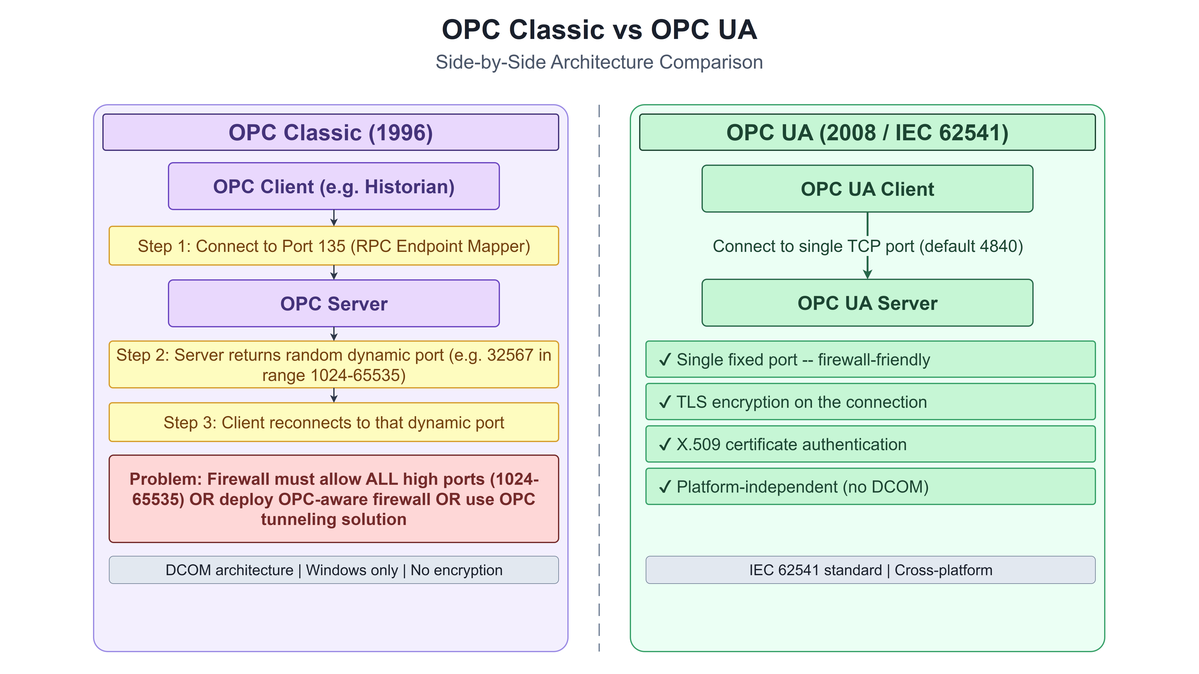
Before 1996, connecting a SCADA system to a Siemens PLC required a Siemens driver. Connecting the same SCADA system to Allen-Bradley required an Allen-Bradley driver. To Schneider, a Schneider driver. Every historian, every reporting tool, every HMI needed custom drivers for each PLC brand. With dozens of vendors on each side of the connection, the integration and maintenance burden was enormous. OPC solved this problem by standardizing the interface. One OPC server per device type. Any OPC client can connect to any OPC server. Instead of N times M custom driver combinations, the industry needed N OPC servers plus M OPC clients. The original OPC Classic standard produced three separate specifications: OPC DA (Data Access) for real-time tag values, OPC HDA (Historical Data Access) for archived data retrieval, and OPC AE (Alarms and Events) for alarm notifications. All three were built on Microsoft Windows DCOM technology, creating a Windows-only dependency that broke across firewalls and made Linux systems and cloud platforms unreachable.
OPC UA, released in 2006, is not an update to Classic -- it is a complete redesign. It runs on Windows, Linux, macOS, and embedded systems. It unifies DA, HDA, and AE into one framework. It communicates over binary TCP on port 4840, HTTPS, or WebSockets. Security is built in and mandatory: authentication, message signing, and encryption are not optional add-ons. OPC UA also models data as typed relationships, so a sensor is linked to the equipment it monitors rather than appearing as an anonymous name-value pair. OPC UA is now the standard connection point from the plant floor to enterprise IT and cloud platforms. Historians like AVEVA PI expose data via OPC UA as a primary interface. Azure IoT Hub, AWS IoT SiteWise, and Siemens Insights Hub connect to plant floor data through OPC UA. Legacy Classic installations use UA wrapper gateways to re-expose existing Classic servers with a standard UA interface, without changing the underlying hardware communication layer. This matters from a security perspective: the OPC UA server is the bridge between the OT network and everything above it, and its configuration determines what data leaves the control network and how it is protected in transit.
Network Topologies: Building for Continuity
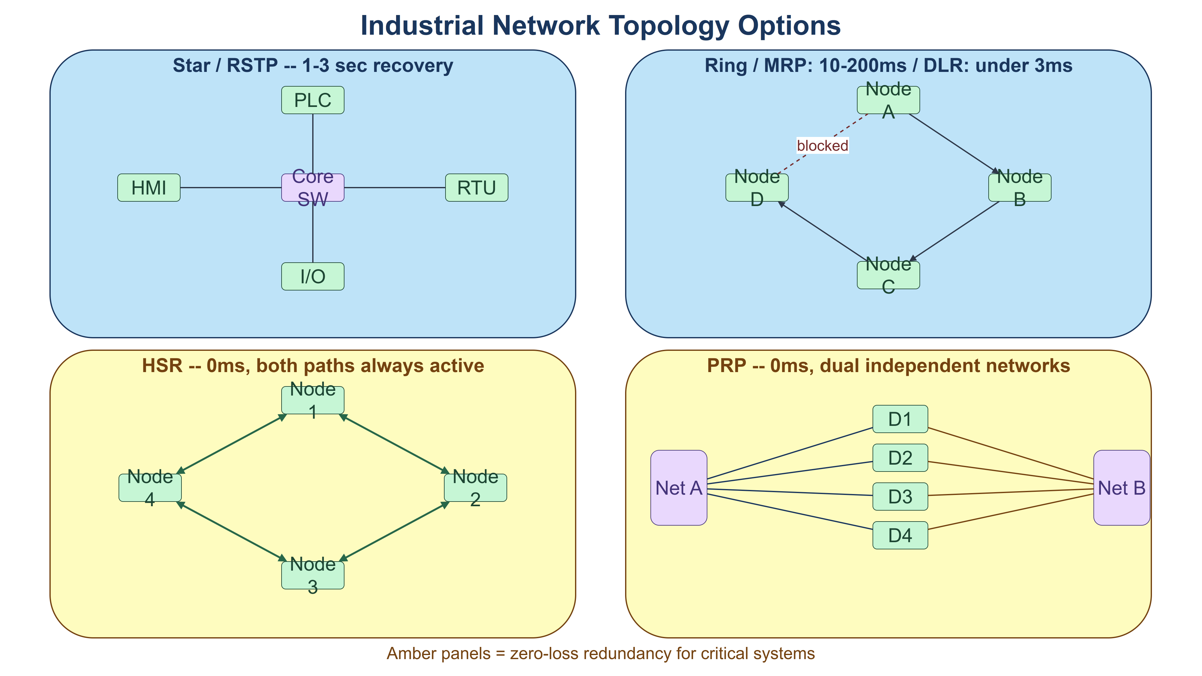
Network topology describes how devices are physically connected and how traffic paths are arranged. In IT environments, most networks use a star topology: devices connect to a central switch, switch failure takes everything down, but individual device failures are contained. Industrial networks need something different, because the consequence of a network failure is not a user losing connectivity -- it is a physical process losing its control inputs. The topology choices in ICS are driven by one requirement above all others: continuity. A ring topology closes a line of devices into a loop, providing a second path for traffic. If one link breaks, traffic reroutes in the other direction. PROFINET uses Media Redundancy Protocol (MRP), achieving 10 to 200 milliseconds recovery. EtherNet/IP uses Device Level Ring (DLR), achieving under 3 milliseconds on rings of up to 50 nodes. Ring topology is the standard for PROFINET and EtherNet/IP device networks in manufacturing. For applications where even milliseconds of recovery time is unacceptable, two protocols eliminate switchover delay entirely. HSR (High-availability Seamless Redundancy, IEC 62439-3) sends every frame simultaneously in both directions around a ring. The receiver takes the first copy and discards the duplicate. Both paths are always active, so a link failure causes no recovery delay -- it is physically imperceptible to the running process. HSR appears in electrical substations, rail systems, and safety-critical applications. PRP (Parallel Redundancy Protocol, IEC 62439-3) goes further: each device has two network cards connected to two completely independent networks, with separate switches, separate cables, and separate paths. Both networks carry every frame simultaneously. If one entire network fails, traffic continues on the other with no interruption. Where HSR protects against single link failures, PRP protects against complete network failure -- at the cost of double the infrastructure.
What Normal OT Traffic Looks Like
An OT network may be the most predictable network you ever monitor. The same devices, the same messages, the same timing -- every day, every week, every year. A Modbus read command (FC03) from the SCADA server to PLC-07 fires every 500 milliseconds. A PROFINET I/O frame from the PLC to a variable frequency drive fires every 10 milliseconds. A Modbus TCP request reading 10 holding registers is 12 bytes long. An entire plant floor network with dozens of PLCs may generate less total bandwidth than one HD video call. OT networks are timing-constrained, not bandwidth-constrained. A mature ICS network also has a fixed communication matrix: a documented map of every authorized connection. PLC-07 communicates with SCADA Server A on port 502 at 192.168.10.7. Nothing else. A new device appearing on that segment is immediately visible. A known device communicating with a PLC it has never addressed before is anomalous. These three properties -- cyclic timing, minimal bandwidth, and a fixed communication matrix -- are what make OT security monitoring fundamentally different from IT security monitoring. In IT environments, "normal" shifts constantly and is too complex to define precisely. In OT, normal is an engineering specification. Commercial OT security monitoring platforms (Dragos, Claroty, and Nozomi Networks are the major ones) exploit this predictability directly: they baseline the traffic, then surface anything that deviates. A Modbus write command from a device that has only ever sent read commands. A polling interval that suddenly triples. A new device address on a segment where nothing new should appear. Any of these is immediately visible in an OT environment because the baseline is precise.
An OT network monitoring tool installed at a water treatment plant might show something like this during normal operations: SCADA Server polling PLC-01 every 500ms on Modbus TCP port 502 (FC03, registers 0-49); PLC-01 polling all six field I/O segments every 10ms via EtherNet/IP; historian writing to a replica every 60 seconds via OPC UA on port 4840; no other connections. Three devices communicating on three protocols, all on expected intervals, all to expected destinations. When an unknown IP address sends an FC16 write command to PLC-01 at 2:14 a.m. -- a Modbus write command from a source that has never appeared before -- the monitoring tool surfaces it immediately, because it doesn't fit the baseline. This is why OT monitoring is tractable in a way that IT monitoring often isn't: the baseline isn't estimated from historical patterns, it's derived from the engineering design. The legitimate communication matrix is defined before the network is built.
What's Next
The first three chapters have built the foundation: what ICS is, how the components work together, and how they communicate. Chapter 4 is where the security content begins. It opens with the threat landscape specific to ICS environments -- the adversaries, their motivations, and the incidents that have defined the field -- before introducing the IEC 62443 framework that structures everything in Part 2 of this book.
Reflect
- Chapter 3 describes three properties of OT traffic (cyclic timing, low bandwidth, fixed communication matrix) that make anomaly detection tractable. Does your organization have a tool in place that monitors OT traffic against a defined baseline? If not, what would need to change to make that possible?
- Multiple industrial protocols almost certainly coexist in your environment -- Modbus, EtherNet/IP, PROFINET, DNP3, and OPC connections can all appear in the same facility. Do you have a complete picture of which protocols are in use and where each one appears?
- OPC UA is the primary bridge between plant-floor data and enterprise systems, with mandatory security features that OPC Classic lacked. If your organization is still running Classic OPC servers exposed to the enterprise network, what is the migration path to UA, and what is the timeline?
- The choice of network topology (ring vs HSR vs PRP) reflects a decision about acceptable recovery time for that segment. For the most critical segments in your environment, do you know what the recovery time is if a switch or link fails -- and is that acceptable for the process it supports?
AI-Prompt Engineering for Strategic Leaders
Stop managing administration and start leading the future. This course is built specifically for managers and project professionals who want to automate chaos and drive strategic value using the power of artificial intelligence.
We don't teach you how to program Python; we teach you how to program productivity. You will master the AI-First Mindset and the 'AI Assistant' model to hand off repetitive work like status reports and meeting minutes so you can focus on what humans do best: empathy, negotiation, and vision.
Learn the 5 Core Prompt Elements-Role, Goal, Context, Constraints, and Output-to get high-quality results every time. You will build chained sequences for complex tasks like auditing schedules or simulating risks, while navigating ethics and privacy with human-in-the-loop safeguards.
Move from being an administrative manager to a high-value strategic leader. Future-proof your career today with practical, management-focused AI workflows that map to your real-world challenges. Enroll now and master the language of the future.
Explore the Course
Lead with clarity, influence, and outcomes.
HK School of Management offers a practical Leadership for Project Managers course for real projects, tight deadlines, and cross-functional teams. Learn to set direction, align stakeholders, and drive commitment without relying on title. Practical skills, tools, and guidance you can apply right away. Covered by Udemy's 30-day refund policy.
Learn More