Chapter 2
ICS Components: PLC, HMI, SCADA, DCS, and More
From Sensor to Management Report
A pressure transmitter in a water pipe reads 87 PSI. Six steps later, that reading appears as a number in a management report on a laptop in a corporate office. Between those two endpoints are every component in an industrial control system, working in sequence, each one handing data or commands to the next. Chapter 1 named those components as you moved through the Purdue Model. This chapter opens each one up and explains what it actually does, how it is built, and where it sits in the architecture. Understanding these components at this level of detail is what makes the security discussions in Part 2 concrete. When you read in a later chapter that an attacker gained access through an engineering workstation, or that a historian was used to exfiltrate operational data, you'll know exactly what was compromised and why it mattered.
The PLC: One Loop, Running Forever
Picture a device about the size of a thick hardcover book. No screen. No keyboard. No user interface of any kind. It runs the same program every 10 milliseconds, 24 hours a day, for 20 to 30 years without interruption. This is a Programmable Logic Controller (PLC): an industrial computer with one purpose -- reading sensor data and sending commands to actuators. Actuators are the physical devices, such as motors, valves, and pumps, that carry out those commands. No web browsing, no multitasking, no background processes. Just one program, in one deterministic loop, running continuously. Deterministic execution is the defining characteristic: the PLC responds within a guaranteed time window on every single cycle, because industrial processes cannot wait for a processor that's busy with something else.
The PLC operates in a four-step scan cycle. First, Input Scan: it reads all sensor states into memory. Second, Program Execution: it runs control logic against that snapshot. Third, Output Update: it writes all results to physical outputs simultaneously, so every output changes from the same input snapshot, keeping the process consistent. Fourth, Housekeeping: communications and diagnostics. Scan cycles typically run between 1 and 50 milliseconds. At 10 milliseconds, the PLC completes 100 full cycles per second. Control logic is most commonly written in ladder logic, a language designed to look like the relay wiring diagrams that electricians were already familiar with before PLCs replaced relay panels in the 1970s. That design decision, making PLC programming look like wiring, is why it still holds the largest share of the PLC programming market decades later. Physically, PLCs range from micro units with 8 to 20 I/O connection points for simple machines, to modular chassis systems with hundreds of points for entire production lines. The dominant vendors are Siemens (S7 series, strong in Europe), Rockwell Automation (Allen-Bradley, dominant in North America), and Schneider Electric (Modicon, widespread in utilities and infrastructure).
The HMI: The Operator's Window
The HMI (Human-Machine Interface) is the display that lets an operator watch and interact with a running industrial process. The critical point: the HMI doesn't control anything directly. The PLC handles the actual control. The HMI shows what's happening and accepts input from the operator, which it passes to the PLC for execution. Think of a car dashboard: it displays the engine status, but the engine management unit handles fuel and ignition. Clicking a button on an HMI sends a command to the PLC, which checks it against safety interlocks before acting. The main display is a process schematic: a simplified diagram of the plant with live values overlaid. Tank levels, pressures, temperatures, valve positions, pump status. Color indicates state at a glance -- green for running, red for fault, grey for stopped. Below the schematic: an alarm list showing every out-of-range condition with timestamps and severity. Trend graphs track key values over time, giving operators the context to distinguish a transient spike from a developing problem. Operators can adjust setpoints within permitted ranges directly from the display.
HMIs come in two forms. Panel HMIs are sealed touchscreen terminals built into a control panel, ruggedized for the plant environment. PC-based HMIs run software such as AVEVA InTouch or Rockwell FactoryTalk View on an industrial PC, connecting to multiple PLCs and providing more flexibility for complex systems. The panel option is simpler and more durable. The PC-based option requires ongoing operating system maintenance -- and therein lies the security challenge. The HMI and PLC communicate by polling: the HMI continuously requests updated values, refreshing every 100 to 500 milliseconds. Common protocols include EtherNet/IP (Rockwell systems), PROFINET (Siemens systems), and Modbus TCP (cross-vendor). OPC-UA, covered in Chapter 11, serves a different role -- bridging HMI data upward to historians and enterprise systems.
SCADA: Supervision Across Distance
A single pump station is manageable with one HMI and one operator. A city water authority managing 40 pump stations scattered across a metropolitan area cannot staff 40 separate control rooms around the clock. SCADA is the solution: one central view of all 40 stations, from one room. As Chapter 1 defined, SCADA (Supervisory Control and Data Acquisition) is software that collects data from remote equipment and sends commands back. Each word in the acronym describes a distinct function: supervisory means it sits above the PLCs and HMIs it watches, not alongside them; control means it can send commands to remote field equipment; data acquisition means it continuously collects readings and stores them in a persistent database. A SCADA system is not a bigger HMI. It is a different category of system, defined by geographic scale and centralized aggregation. A local HMI tracks 1,000 to 5,000 tags (a tag is a single named data point: one pressure reading, one valve state). A SCADA system handles tens of thousands to hundreds of thousands. Local HMIs store data only in RAM; SCADA writes to a persistent database that supports historical queries. Common platforms include AVEVA System Platform (formerly Wonderware), Rockwell FactoryTalk View SE, Inductive Automation Ignition, and Schneider GeoSCADA, which is built specifically for geographically dispersed infrastructure where communication links may drop periodically.
The DCS: When One Vendor Does Everything
Two engineers are designing a new facility. One selects PLCs from one vendor, SCADA software from a second, and a historian from a third. They spend months integrating those components. The other engineer orders an Emerson DeltaV: one vendor, one call, one integrated system. This is the fundamental distinction of a Distributed Control System (DCS). A DCS is a single-vendor, fully integrated control platform. One vendor supplies the controllers, operator stations, historian database, configuration software, and alarm management, all designed to work together without custom integration. The tradeoff is vendor lock-in: you are committed to one company's upgrade roadmap. The benefit is operational reliability at scale, which is why DCS platforms dominate environments where custom integration failure at startup is simply not acceptable.
The choice between PLC-based systems and a DCS comes down to process type. PLC systems handle discrete, sequential control: make parts, assemble products, do step A then step B. DCS systems handle continuous process control, where control loops run without stopping. A control loop is a feedback cycle in which the controller reads a process value, compares it to a target, and continuously corrects the difference. A large oil refinery runs thousands of these loops simultaneously. At that scale, a pre-integrated DCS is the practical choice. The dominant platforms are Honeywell Experion PKS (leading in refining and petrochemical), Emerson DeltaV (strong in oil and gas, chemicals, and life sciences), ABB 800xA (mining, metals, pulp and paper), and Yokogawa Centum VP (Asian refining and petrochemical markets). The word "distributed" in the name refers to the architecture: rather than placing all control hardware in one central room with hundreds of meters of wiring running to sensors and valves throughout the plant, a DCS places multiple controllers throughout the facility, each close to its process area.
RTUs and Field Devices
A gas pipeline valve station 80 kilometers from the nearest town has no reliable grid power, no wired network, and no local operator. But the SCADA operator in the central control room can see that valve's status and close it remotely if needed. The device making that possible is a Remote Terminal Unit (RTU): a ruggedized field device built for unattended remote operation. The RTU reads local sensor data and transmits it to the central SCADA system via radio, cellular, or satellite. If the communication link drops, the RTU buffers readings locally and uploads them when connectivity is restored. This data buffering is a capability PLCs don't have natively, which is why RTUs exist as a distinct category. Two telemetry protocols handle most RTU deployments globally: DNP3 in electric utilities and water systems, and Modbus RTU in oil and gas and other sectors. RTU hardware typically runs on solar panels or batteries, operates across wide temperature ranges, and requires no local intervention for years at a time.
Field devices are the sensors and actuators that connect the digital control system to the physical process. Sensors convert physical measurements into electrical signals. Field transmitters send those signals over wire using one universal standard: the 4 to 20 milliamp (4-20mA) current loop. A pressure transmitter measuring 0 to 100 PSI outputs 4mA at 0 PSI and 20mA at 100 PSI. The lower bound is deliberately not zero: if the minimum signal were 0mA, a broken wire would be indistinguishable from a valid zero reading. The 4mA "live zero" prevents that ambiguity. Common sensor types include pressure transmitters, temperature transmitters (using RTDs or thermocouples), flow meters (magnetic, ultrasonic, or Coriolis types), and level transmitters (radar or ultrasonic). Actuators receive commands from the PLC and act on the process. Control valves throttle flow in proportion to a 4-20mA input signal: in a fail-closed configuration, 4mA is fully closed and 20mA is fully open. Variable frequency drives control motor speed by varying the electrical frequency. Motor starters and contactors start and stop motors on discrete on/off commands. These instruments, small enough to hold in one hand, are the foundation of every control loop in every industrial facility in operation today.
Engineering Workstations and Historians
Two computers sit at Level 3 of the Purdue Model that most operators never touch. The first is the engineering workstation: an industrial PC used by automation engineers and instrument technicians to write the programs that tell PLCs what to do. It runs vendor-specific engineering software -- Siemens TIA Portal for S7 PLCs, Rockwell Studio 5000 for Allen-Bradley, Emerson DeltaV Control Studio for DeltaV controllers. Engineers use it to write control logic, build HMI screen configurations, maintain the I/O tag database (the catalog of every sensor and actuator the system recognizes), run diagnostics, and push updated programs to controllers. The engineering workstation has direct, programming-level access to every PLC it manages. An engineer can connect to a controller, load a modified program, and deploy it in seconds, without operator approval. This is the most powerful and most dangerous access point in the entire control network. In 2010, the Stuxnet cyberattack spread through engineering workstations to reach and reprogram PLCs at uranium enrichment facilities, demonstrating precisely why this access point matters from a security perspective. The full Stuxnet story is told in Chapter 4.
The second Level 3 component is the historian: a specialized database built for industrial time-series data. Standard relational databases are not designed for the volume and pattern of ICS measurements -- thousands of tagged values, each timestamped, recorded continuously for years. Historians use compression algorithms that store only the points where a value changes meaningfully, reducing storage requirements by up to 90 percent without losing measurement fidelity. The dominant platform globally is the AVEVA PI System (formerly OSIsoft PI). What the historian records is comprehensive: every sensor reading with its timestamp, every state change (pump 4 stopped at 14:33:11), every alarm with when it fired and when it cleared, batch records for regulated industries (every temperature setpoint and chemical dose, permanently timestamped for compliance), and calculated production KPIs. Engineers can retrieve any of this data years after an event and replay the trends leading up to any process upset. The historian sits at Level 3 precisely because it aggregates process data from across the plant before that data crosses the boundary into the enterprise network above.
How the Architecture Fits Together
Trace the path of that 87 PSI reading from the field to the corporate office. The pressure transmitter outputs a 4-20mA signal that the PLC converts to a digital value at Level 1. The scan cycle runs, the PLC publishes its values to the control network, and the SCADA server at Level 2 collects them alongside thousands of other readings from dozens of PLCs. The HMI at Level 2 displays the live value for the operator. At Level 3, the historian records the reading with its timestamp, storing it permanently. Commands travel the reverse path: an operator at the SCADA workstation raises a setpoint, the SCADA server sends the command to the PLC, and the PLC's Output Update step writes the new value to the appropriate actuator at Level 0.
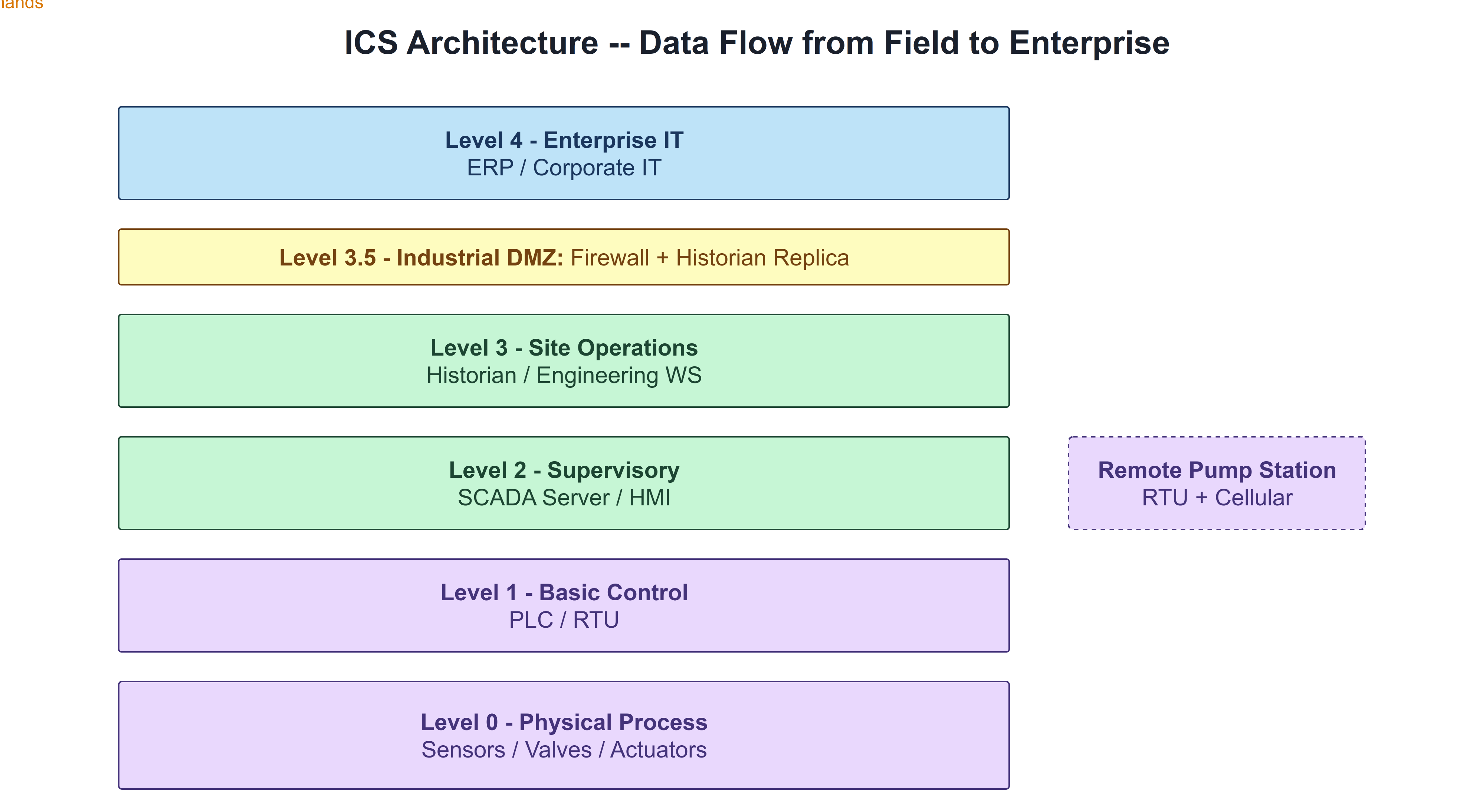
Between Level 3 and the enterprise network above sits the Industrial DMZ at Level 3.5: a security boundary enforced by firewalls on both sides. The historian pushes data to a replica in the DMZ. Enterprise systems pull from that replica. No enterprise system connects directly into the control network, and no control network device connects directly into the enterprise. This architecture ensures that a compromise of the enterprise network does not give an attacker direct access to PLCs and field devices. Each level boundary in the Purdue Model serves this purpose -- limiting how far a fault, or an intrusion, can propagate.
A municipal water treatment plant uses every component covered in this chapter. At Level 0, 4-20mA sensors measure pressure, flow, turbidity, and chemical concentrations at every stage. At Level 1, six PLCs handle control for each treatment stage: intake, screening, coagulation, filtration, chlorination, and distribution pumping. At Level 2, a SCADA server aggregates readings from all six PLCs, and two operator workstations in the control room show the complete plant view. Remote pump stations scattered across the distribution network connect via RTU and cellular radio, feeding into the same SCADA view at Level 2. At Level 3, a historian records every sensor reading and alarm for EPA compliance reporting, and an engineering workstation is accessed only when control logic needs to change. The historian pushes data across the DMZ to a replica used by the utility's business systems. One facility, one architecture, all eight component types working in sequence.
The Weak Points These Components Carry
Chapter 1 established the structural security gaps in ICS: protocols without authentication, the erosion of the air gap, legacy hardware without available patches, and the absence of network monitoring. At the component level, those gaps have specific faces. The engineering workstation carries the most concentrated access risk: it has programming-level access to every controller on the network, often runs an operating system that requires vendor approval before patching, and is frequently accessed by automation engineers using credentials shared across multiple tools and systems. The HMI, particularly the PC-based variant, runs an operating system that needs patches on a timeline the plant environment may not permit, while also being one of the most-accessed machines on the control network. Vendors connect to it remotely for support. Operators use it every shift. It is often the most connected and least-maintained system in the control network. The historian sits at the boundary between the OT world and the enterprise network, making it a natural target for data exfiltration: an attacker who reaches the historian has access to years of operational data describing exactly how the facility works. Each of these components is examined again in Part 2, this time through the lens of how attackers approach them and what defenses are practical within operational constraints.
What's Next
Chapter 2 has filled in the components. Chapter 3 covers the networks that connect them: the industrial protocols that PLCs and SCADA systems use to communicate, how those networks are physically structured, and what normal ICS traffic looks like -- because understanding what normal looks like is a prerequisite for recognizing when something is wrong.
Reflect
- Think about the control system in your own environment. Which of the components covered in this chapter are present, and which do you interact with directly? Are there components you now realize you've been working around without fully understanding their role?
- The engineering workstation has direct, unrestricted access to every PLC it manages and often runs an operating system that lags on patches. How is access to the engineering workstation managed in your environment -- and is that management adequate for the level of access it grants?
- The historian sits at the boundary between OT and enterprise IT, making it a natural exfiltration point. What data does your historian hold, who can access it from the enterprise side, and through what controls?
- The Industrial DMZ is designed to prevent enterprise-side compromises from reaching the control network directly. Is the DMZ architecture in your environment enforced as strictly as this chapter describes, or have direct connections accumulated over time?
Leadership for Project Managers Course
Lead with clarity, confidence, and real impact. This Leadership for Project Managers course turns day-to-day challenges—unclear priorities, tough stakeholders, and cross-functional friction—into opportunities to guide teams and deliver outcomes that matter.
You’ll learn practical leadership skills tailored to project realities: setting direction without overcontrol, creating alignment across functions, and building commitment even when authority is limited. We go beyond theory with tools you can use immediately—one-sentence visioning, stakeholder influence maps, decision framing, and feedback scripts that actually land.
Expect hands-on frameworks, real-world examples, and guided practice to prepare for tough moments—executive readouts, resistance from stakeholders, and high-stakes negotiations. Downloadable templates and checklists keep everything actionable when the pace gets intense.
Learn alongside professionals around the world working in project leadership and delivery.
Explore the Course
Advance your Lean Six Sigma expertise!
HK School of Management helps you take Lean Six Sigma to the next level without the overwhelm. Master advanced statistical tools, Excel-based analysis, and real-world improvement techniques to solve complex problems with confidence. Practical skills, tools, and guidance you can apply right away. Covered by Udemy's 30-day refund policy.
Learn More